Begin with what moves through the process
A tray of discrete samples, a large supported casting and a stream of granules may all require thermal treatment. They do not create the same furnace duty. The first selection question is how the material is held and moved: stationary in a chamber, carried on a trolley or transported and mixed within a rotating tube.
Our equipment range includes Muffle Furnace, Car Bottom Furnace and Rotary Tube Furnace project directions. Their names identify different arrangements, while the actual heating conditions and supplied components remain specific to the proposed process. A steel-melting furnace specification should not be transferred to these treatment duties.
Compare the three load arrangements
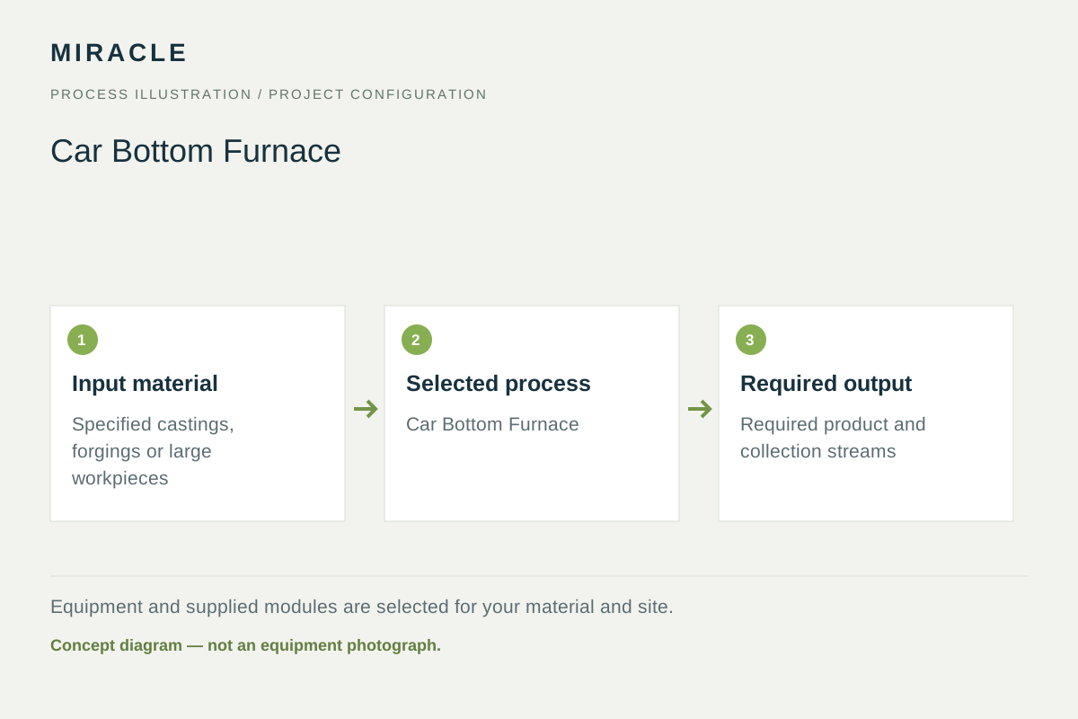
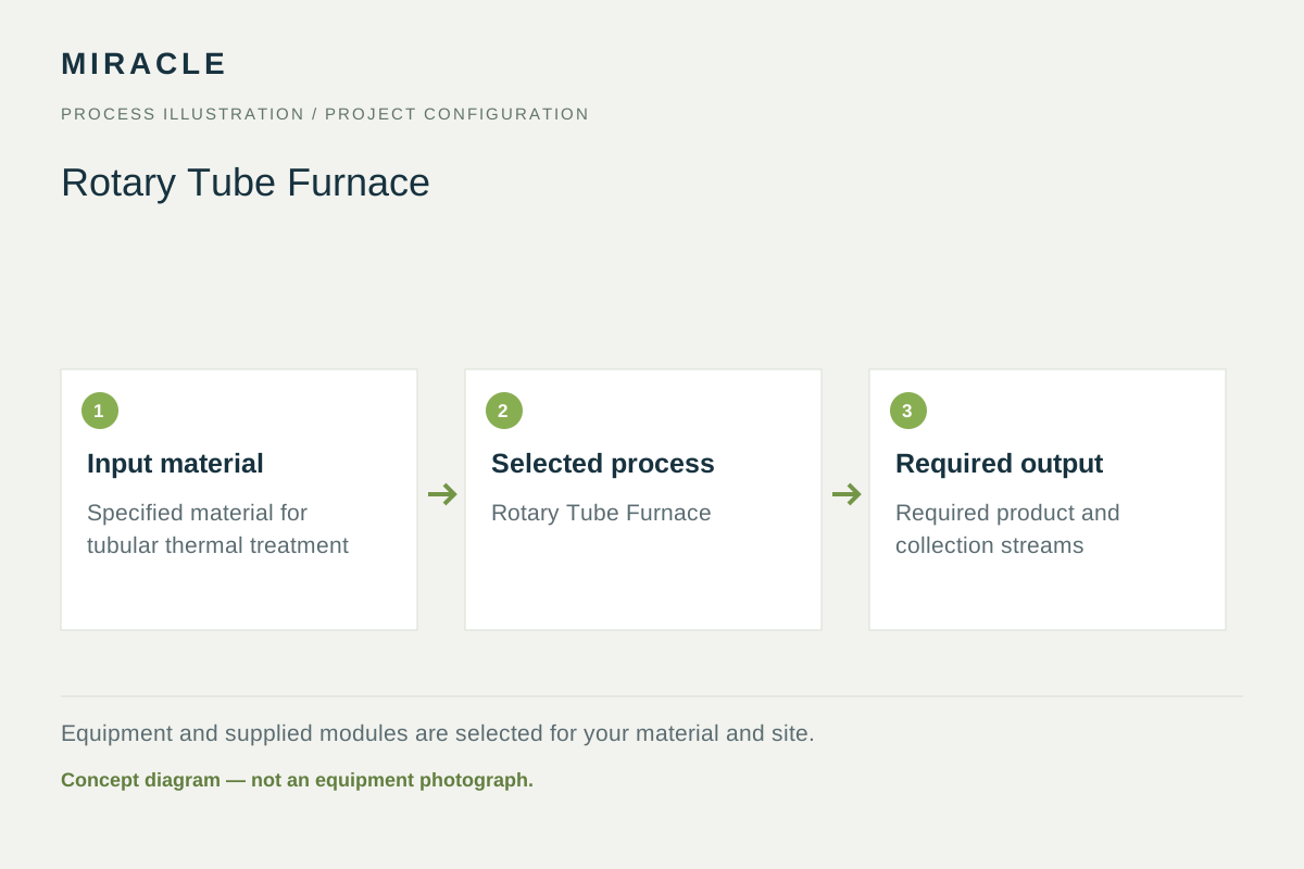
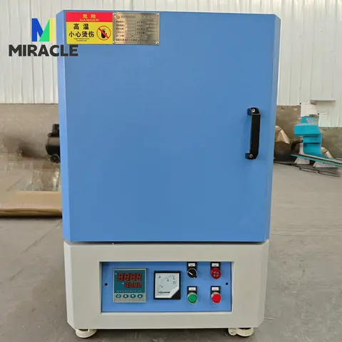
A chamber arrangement holds a defined load during treatment. A car-bottom arrangement makes the supported hearth part of the loading route, allowing the workpiece to be positioned outside the treatment chamber. A rotary tube introduces material movement within the treatment space; suitable designs can address batch or continuous duties.
These differences affect more than the floor plan. They determine what the equipment must support, how material reaches the heated space and what constitutes a useful production unit.
| Furnace direction | Load arrangement to discuss | Useful selection question |
|---|---|---|
| Muffle / chamber | Defined items or containers placed in a chamber | What usable loading space and arrangement does the treatment require? |
| Car bottom | Supported workpieces loaded on a moving hearth | How will parts, fixtures and the trolley move through the workshop? |
| Rotary tube | Particulate material moving within a rotating tube | How does the material flow and behave during the intended thermal duty? |
Treat chamber size and useful load as different information
The external dimensions of a part do not describe the complete load. Trays, containers, supports and fixtures also occupy space. A chamber chosen from the largest bare component may leave an unsuitable loading arrangement once those items are included. Show the loaded arrangement, not only the product drawing.
For a trolley furnace, include the supported workpieces and the access required to position them. For a rotary tube, describe particle size, flow behavior and changes expected during treatment. Material that moves freely before heating may behave differently when hot; that behavior belongs in process selection rather than being assumed from its room-temperature appearance.
State the thermal objective separately from the handling method
The loading arrangement does not establish the required treatment. Identify whether the project concerns a specified material test, heat treatment or another defined thermal operation. Provide the process requirement supplied by the responsible material or production specialist, including what result will be checked.
A controller setting and the temperature reached throughout a real load are different pieces of information. Define the required working zone, load arrangement and recording or assessment method. The label muffle does not alone establish a particular atmosphere, and a rotary tube does not automatically include a complete process-gas package.
Compare production on the appropriate basis
For a batch chamber or trolley arrangement, describe the load per cycle and the available production period. The complete cycle includes handling and the agreed treatment sequence. A larger chamber does not by itself demonstrate a proportionally larger finished output.
For continuous tube processing, distinguish incoming feed rate, time within the treatment zone and collected output. Rotation, inclination and the feed arrangement can influence material movement, but they are configuration variables to evaluate with the actual material. Do not convert a chamber volume or a hopper size into a guaranteed production rate.
Build a proposal around the material path
A useful proposal links the incoming load, treatment space and receiving operation. For discrete samples, show the container layout. For a large workpiece, show the support and trolley route. For particulate treatment, show feeding and collection. These sketches reveal equipment interfaces that a furnace name leaves unresolved.
- Describe the material, physical form and required treatment outcome.
- Show the complete load, including containers or supports.
- Identify batch or continuous production and the basis of the target output.
- List required handling, controls and process-environment components as individual scope items.
Before you decide
Is a car-bottom furnace simply a larger muffle furnace?
The moving hearth changes the loading and support arrangement. Compare the workpiece, fixtures, treatment duty and workshop route before deciding whether either chamber arrangement fits the project.
Does every rotary tube furnace operate continuously?
Rotating-tube equipment can be arranged for batch or continuous work. Specify the material movement and feeding requirement, then establish which arrangement is proposed.
Equipment references
Product information for the equipment discussed in this guide.